Two in One Drawlings Old Fashioned Train With a Big Light in the Front
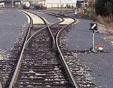
A right-mitt railroad switch with point indicator pointing to right
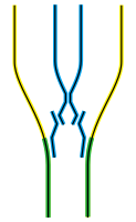
Animated diagram of a right-hand railroad switch. Track track A divides into ii: track B (the straight rail) and track C (the diverging track); note that the dark-green line represents management of travel merely, the blackness lines represent fixed portions of track, and the red lines draw the moving components

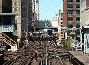
Large stations may have hundreds of normal and double switches (Frankfurt am Master Primal Station).


A railroad switch (AE), turnout, or [set of] points (BE) is a mechanical installation enabling railway trains to be guided from i track to another, such as at a railway junction or where a spur or siding branches off.
A switch (points) consist of a pair of linked tapering rails, known as points (switch track or point blades), lying between the diverging outer rails (the stock rails). These points tin be moved laterally into i of two positions to direct a train coming from the point blades toward the straight path or the diverging path. A train moving from the narrow terminate toward the point blades (i.e. information technology volition be directed to one of the two paths, depending on the position of the points) is said to be executing a facing-betoken movement.
Unless the switch is locked, a train coming from either of the converging directs will pass through the points onto the narrow cease, regardless of the position of the points, equally the vehicle'southward wheels will force the points to movement. Passage through a switch in this management is known as a trailing-point motion.
A switch generally has a directly "through" track (such as the main-line) and a diverging route. The handedness of the installation is described by the side that the diverging track leaves. Right-hand switches accept a diverging path to the correct of the straight track, when coming from the point blades, and a left-handed switch has the diverging rail leaving to the opposite side. In many cases, such as rail yards, many switches can be constitute in a short section of rails, sometimes with switches going both to the right and left (although it is better to proceed these separated equally much as feasible). Sometimes a switch just divides one runway into ii; at others, it serves as a connectedness between two or more parallel tracks, assuasive a train to switch between them. In many cases, where a switch is supplied to get out a track, a 2nd is supplied to let the train to reenter the track some distance downwardly the line; this allows the track to serve every bit a siding, assuasive a train to go off the track to let traffic to pass (this siding can either be a dedicated short length of track, or formed from a department of a second, continuous, parallel line), and also allows trains coming from either direction to switch between lines; otherwise, the only mode for a train coming from the opposite direction to use a switch would be to terminate, and contrary through the switch onto the other line, and and so proceed forwards (or finish, if it is existence used every bit a siding).
A straight rails is not always present; for case, both tracks may curve, one to the left and one to the correct (such every bit for a wye switch), or both tracks may curve, with differing radii, while still in the same direction.
History [edit]
On early lines, vehicles were moved betwixt tracks by ways of sliding rails. The switch was patented by Charles Fox in 1832.
Prior to the widespread availability of electricity, switches at heavily travelled junctions were operated from a signal box constructed near the tracks through an elaborate system of rods and levers. The levers were likewise used to control railway signals to control the movement of trains over the points. Eventually, mechanical systems known every bit interlockings were introduced to make sure that a signal could just be set to allow a train to go on over points when it was safe to do so. Purely mechanical interlockings were eventually adult into integrated systems with electric command. On some depression-traffic branch lines, in self-independent marshalling yards, or on heritage railways, switches may still have the earlier type of interlocking.
Operation [edit]

The operation of a railroad switch. In this blitheness, the red track is the one travelled during a facing-indicate motility. The switch mechanism, shown in blackness, may be operated remotely using an electric motor or manus-operated lever or from a nearby ground frame.
A railroad motorcar'due south wheels are guided along the tracks by coning of the wheels.[ane] Merely in extreme cases does information technology rely on the flanges located on the insides of the wheels. When the wheels reach the switch, the wheels are guided forth the route determined by which of the two points is connected to the rails facing the switch. In the illustration, if the left signal is connected, the left wheel will exist guided forth the rail of that point, and the railroad train volition diverge to the right. If the right point is connected, the right wheel's flange will be guided along the track of that point, and the train will keep along the straight rail. But one of the points may exist connected to the facing track at any time; the two points are mechanically locked together to ensure that this is ever the case.
A mechanism is provided to motility the points from one position to the other (change the points). Historically, this would require a lever to be moved by a homo operator, and some switches are still controlled this way. However, about are now operated by a remotely controlled electric motor or past pneumatic or hydraulic actuation, called a bespeak machine. This both allows for remote control and for stiffer, strong switches that would exist too difficult to move by hand, however allow for higher speeds.
In a trailing-betoken movement (running through the switch in the incorrect management while they are ready to turn off the track), the flanges on the wheels volition force the points to the proper position. This is sometimes known every bit running through the switch. Some switches are designed to be forced to the proper position without damage. Examples include variable switches, spring switches, and weighted switches.
If a switch becomes worn or the operating rods become damaged, it is possible for the flange to split the switch, and go through the switch in the direction other than what was expected. This happens when the flange strikes a modest gap between the stock-still rail and the set switch bespeak (whichever is touching the main line); this forces the switch open, and the train is diverted down the incorrect rails. This can either happen to the locomotive, in which example the whole railroad train tin be directed onto the incorrect track, with potentially unsafe results, or it can occur at any point through the railroad train, when a random truck is directed downwards a dissimilar track from the rest of the train; if this happens on the front truck of a motorcar, the usual result is derailment, as the trailing truck of the preceding car attempts to go i way, while the leading truck of the following motorcar tries to get another. If it happens to the trailing truck of a machine, the front truck will follow i rail, while the trailing truck follows a parallel line; this causes the whole machine to "crab", or move sideways downwards the track (derailment frequently results eventually, due to the lateral forces applied when the train tries to restriction or accelerate). This tin have disastrous results if there is whatever obstacle between the lines, every bit the car will exist propelled into information technology sideways, such as happened in the 1928 Times Square derailment. In some cases, the whole train behind the car volition follow the errant machine onto the other rails; in others, merely ane or a few trucks are diverted, while the residual follow the right rail. In cases where information technology is a simple siding, rather than a continuous parallel track, the diverted truck(s) can travel the whole length of the siding until it turns back to the principal track, where it performs a abaft point motility, forces the switch open, and ends up back on the same track again, with only damage to the switches. This is far less likely in cases of diversion to a parallel runway, since switches on both lines will often be interconnected, and then to set the switch on the main line to straight-through will set the other switch to straight-through also (otherwise there is a take a chance of turning off the track only to find the joining switch is ready the wrong way, and running the train through it). Because derailments are expensive and very unsafe to life and limb, maintenance of switch points and other trackwork is essential, particularly with faster trains. Another derailment that occurred due to a split switch is the ProRail Hilversum derailment on 15 January 2014.
If the points are rigidly connected to the switch control mechanism, the control mechanism's linkages may be aptitude, requiring repair before the switch is once more usable. For this reason, switches are normally set to the proper position before performing a trailing-point motility.[2]
An example of a mechanism that would require repair after a run-through in the trailing direction is a clamp-lock. This mechanism is popular in the U.k., but the damage acquired is common to most types of switches.
It would be possible, at least theoretically, to build a rail switch with linkages potent plenty that they would non bend under the force of the flanges of train wheels pushing one of the points away from the side by side fixed rail, and so that the points would never motion during a trailing-indicate motion, at least as long as the speed of the train was not excessive. And so, in a abaft-point movement along the road that the points were not set to, the switch would not be damaged, merely instead the train would derail. Obviously, it is preferable for the switch to give style and be damaged than for the train to derail, causing damage to it and possible injury or loss of life to people aboard the train or nearby.
High-speed operation [edit]
Mostly, switches are designed to be safely traversed at depression speed. Nevertheless, it is possible to alter the simpler types of switch to allow trains to pass at loftier speed. More complicated switch systems, such equally double slips, are restricted to low-speed functioning. On European high-speed lines, information technology is not uncommon to detect switches where a speed of 200 km/h (124 mph) or more than is immune on the diverging branch. Switches were passed over at a speed of 560 km/h (348 mph) (straight) during the French world speed run of April 2007.[3]
The conventional style to increase turnout speeds is to lengthen the turnout and use a shallower frog angle.[ commendation needed ]
The US Federal Railroad Administration has published the speed limits for higher-speed turnouts with No. 26.five turnout that has speed limit of 60 miles per hour (97 km/h) and No. 32.7 with speed limit of 80 miles per hour (129 km/h).[4]
Operation in cold conditions [edit]
Gas heating keeps a switch gratis from snow and ice.

Similarly, an electric forced-air heater can keep a switch free from snow and water ice.
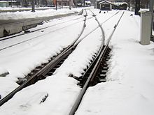
Under cold weather weather condition, snow and ice tin forbid the proper movement of switch or frog betoken rails, essentially inhibiting the proper operation of railroad switches. Historically, railway companies have employees keep their railroad switches clear of snow and water ice by sweeping the snow abroad using switch brooms (Basically wire brooms with a chisel attached onto the opposite end of the broom - quite similar to ice scrapers used today), or gas torches for melting water ice and snow. Such operation are still used in some countries, particularly for co-operative routes with but limited traffic (e.thousand. seasonal lines). Modernistic switches for heavily trafficked lines are typically equipped with switch heaters installed in the vicinity of their indicate rails then that the point rail volition not exist frozen onto the stock rail and can no longer move. These heaters may have the form of electric heating elements or gas burners mounted on the rail, a lineside burner blowing hot air through ducts, or other innovative methods (east.g. geothermal estrus sink, etc.) to go along the signal & stock rails above freezing temperatures. Where gas or electric heaters cannot be used due to logistic or economic constraints, anti-icing chemicals can sometimes be applied to create a barrier between the metallic surfaces to prevent water ice from forming between them (i.e. having frozen together by water ice). Such approaches however, may not always be effective for extreme climates since these chemicals will be washed away over time, especially for heavily thrown switches that experience hundreds of throws daily.
Heating alone may non always be enough to keep switches functioning under snowy conditions. Wet snow conditions, which generate especially gummy snow and whiteout conditions, may occur at temperatures just below freezing, causing chunks of ice to accumulate on trains. When trains traverse over some switches, the daze, vibration, possibly in combination with slight heating caused past braking or a city microclimate, may cause the chunks of water ice to fall off, jamming the switches. The heaters need time to melt the water ice, then if service frequency is extremely high, there may non be enough time for the ice to cook before the next railroad train arrives, which volition then issue in service disruptions. Possible solutions include installing higher capacity heaters, reducing the frequency of trains, or applying anti-icing chemicals similar ethylene glycol to the trains.[5]
Nomenclature [edit]

A low-speed #6 right-mitt switch between a principal line and a rails yard
The divergence and length of a switch is adamant by the bending of the frog (the betoken in the switch where two rails cross, encounter beneath) and the bending or curvature of the switch blades. The length and placement of the other components are adamant from this using established formulas and standards. This deviation is measured as the number of units of length for a single unit of separation.
In North America this is mostly referred to as a switch'south "number". For example, on a "number 12" switch, the track are 1 unit autonomously at a distance of twelve units from the center of the frog.
In the United Kingdom points and crossings using chaired bullhead rail would be referred to using a alphabetic character and number combination. The letter would ascertain the length (and hence the radius) of the switch blades and the number would define the bending of the crossing (frog). Thus an A7 turnout would exist very brusk and probable only to be found in tight places like dockyards whereas an E12 would be found as a fairly high speed turnout on a mainline.
On the London, Midland and Scottish Railway, switch curvatures were specified from A (sharpest) to F (shallowest), with the following corresponding radii:[vi]
- B - 613 feet (186.84 m) - simple crossover with a 1 in viii crossing angle
- C - 980 anxiety (298.70 m) - scissors or simple crossover with a one in 10 crossing angle
- D - one,379 anxiety (420.32 thousand) - double rail junction switch with a ane in 12 crossing angle
Safety [edit]
Switches are necessary for the operation of a railway, merely they exercise pose a number of risks:
- Reversing the points under a moving train volition almost always derail the railroad train.
- Points might motion due to the farthermost forces exerted past a passing train. In an especially noteworthy and extreme case, a switch's setting was forcibly inverse as a result of a disintegrated duo block bicycle getting caught in a switch. This caused 1 of the world'south worst runway disasters, the Eschede derailment.
- A railroad train might stand so close to the frog of a switch that a passing railroad train would collide with its side (the starting time railroad train is then said to accept been fouling the switch).
- The necessary maintenance of the complex mechanical device might be neglected.
- Tampering with a manually operable switch or operation errors in an interlocking may result in 2 trains being on the same runway, potentially causing a collision.
To minimize accidents caused by these risks, suitable technical remedies as well as certain practices are practical. The most of import are:
- Locks to forbid reversing a switch without a proper key.
- Interlockings that allow signals only to be cleared when switches are set correctly.
- Track circuits to prevent reversing when a passing train is detected.
- Signal locks or clamps that prevent movement of blades by locking them to the stock rail in a secure manner.
- Track circuits and fouling markers to indicate out fouling vehicles.
- Maintenance schedules, especially for measuring deviations of critical distances.
Accidents [edit]
Switch-related accidents caused past one or more than of these risks accept occurred, including:
- The 1980 Buttevant Rail Disaster at Buttevant, County Cork, in Ireland, when the Dublin–Cork limited was derailed at high speed after being inadvertently switched into a siding via ground frame operated points, resulting in 18 deaths.
- Wrecks caused by switches being thrown open in front of the trains by saboteurs, every bit in the non-fatal derailments almost Newport News, on August 12, 1992, and in Stewiacke, on April 12, 2001. To preclude these incidents, nearly unused switches are locked upwardly.
- The 1998 Eschede train disaster in Germany was 1 of the world'due south deadliest high-speed train accidents, resulting in over 100 deaths. It occurred when a wheel rim failed at 200 km/h (125 mph), partially derailing the auto. The bicycle rim went through the floor of the carriage and was dragging on the footing. On arrival at the junction information technology threw the switch, causing the rear wheels of the car to switch onto a rails parallel to the track taken by the front wheels. The automobile was thereby thrown into and destroyed the piers supporting a 300-tonne roadway overpass.
- The May 2002 Potters Bar rail crash at Potters Bar, Hertfordshire, in the United Kingdom, occurred when a switch sprang to a different position as a omnibus crossed information technology, a type of mishap called splitting the switch. The forepart wheels of a coach progressed forth the directly rail as intended, but the rear wheels slewed along the diverging rail. This acquired the whole coach to detach from the train and slew sideways across the platform alee. The movement of the switch occurred beneath the final double-decker, so that the preceding coaches remained on the track. Poor maintenance of the points was found to be the principal crusade of the crash.
- The initial conclusion of the inquiry into the Grayrigg derailment of Feb 23, 2007, blames an incorrectly maintained gear up of points.
- 2 fatal accidents involving the Amtrak Silver Star rider train in South Carolina caused by switches either malfunctioning or misaligned.
- On July 31, 1991, several cars batty killing 7 passengers, due to a missing locking pin on the switch machinery.[7]
- Seventeen years later, on August iv, 2018, the Silvery Star crashed into a parked freight train on a siding due to a misaligned switch, killing two crewmen.[8]
Components [edit]

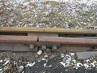
This detail of a switch shows the pair of tapered moveable rails known as the switch points (switch rails or betoken blades).
Points (point blades) [edit]


The points (switch rails or signal blades) are the movable rails which guide the wheels towards either the directly or the diverging track. They are tapered on nearly switches, but on stub switches they have foursquare ends.
In the United kingdom of great britain and northern ireland and Republic countries, the term points refers to the unabridged mechanism, whereas in North America the term refers merely to the movable rails.
In some cases, the switch blades tin can exist heat treated for improvement of their service life. There are different kinds of heat handling processes such as edge hardening or consummate hardening.
The cross-section of the switch blades as well influences performance. New tangential blades perform better than erstwhile-mode blades.
Frog (mutual crossing) [edit]

A one-piece cast frog. The shiny line crosses the rusty line. This N American "self-guarding cast manganese" frog without guard rails has raised flanges on the frog, bearing on the face of the cycle as information technology passes through the frog.

The frog (left) and baby-sit track (right) of a switch
The frog, also known as the mutual crossing (or V-rails in Australian terminology), is the crossing betoken of two rail. This can exist assembled out of several appropriately cut and aptitude pieces of track or tin can be a single casting of manganese steel. On lines with heavy use the casting may be treated with explosive shock hardening to increment service life.[ix]
On lines with heavy or high-speed traffic, a swingnose crossing (movable-point frog) may be used. As the name implies, there is a 2nd machinery located at the frog. This moves a small portion of rail, to eliminate the gap in the rail that normally occurs at the frog. A split switch motorcar is required to operate the movable-point frog switch.[ citation needed ]
This term frog is taken from the part of a horse's hoof information technology about closely resembles. Certain types of overhead electrification systems that make use of trolley poles take similar devices referred to every bit wire frogs.
On dual-guess switches, a special frog is used where the third rail crosses the common rails. Denver and Rio Grande crews called this a "toad".
A recent evolution[ when? ] on Due north American freight railroads is the flange-bearing frog, in which the bicycle flange supports the weight of the vehicle as opposed to the tread. This design reduces bear upon loading and extends the life of the frog.[ citation needed ]
Guard rail (check rail) [edit]
A baby-sit runway (check rail) is a brusk piece of rail placed alongside the principal (stock) runway opposite the frog. These ensure that the wheels follow the appropriate flangeway through the frog and that the railroad train does not derail. Generally, in that location are ii of these for each frog, one by each outer rail. Guard track are non required with a "self-guarding bandage manganese" frog, as the raised parts of the casting serve the same purpose.[ citation needed ]
Bank check rails are often used on very precipitous curves, even where there are no switches.[10]

The switch motor (in this case an electrical motor) and associated mechanism used to operate this switch can be seen to the correct in the flick.
Switch motor [edit]
A switch motor (also known equally a switch machine, betoken motor, signal machine, or automater) is an electric, hydraulic or pneumatic mechanism that aligns the points with one of the possible routes. The motor is commonly controlled remotely past the dispatcher (signaller in the Great britain). The switch motor also includes electric contacts to detect that the switch has completely set and locked. If the switch fails to exercise this, the governing bespeak is kept at red (stop). There is also ordinarily some kind of manual handle for operating the switch in emergencies, such as power failures, or for maintenance purposes.
A patent by W. B. Purvis dates from 1897.

An example of a machinery used at a switch. The two points are linked together with a throw bar (besides known as a stretcher bar). The throw bar extends to the lever on the well-nigh side of the track, which is used to throw the switch. This is an example of a low switch stand, used at locations where there is not sufficient clearance for a tall switch stand up. This particular stand is designed to be trailed through past rolling stock, which will crusade the points to get lined for the route that the wheels take passed through. Information technology has a reflectorised target.

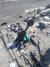
The transmission switch of track bulldoze manufactured by Walter Hoene, the port of Gdańsk earlier 1945, located on the site of the former fuel depot
Points lever [edit]
A points lever, footing throw, or switchstand is a lever and accompanying linkages that are used to marshal the points of a switch manually. This lever and its accompanying hardware is usually mounted to a pair of long sleepers that extend from the switch at the points. They are ofttimes used in a identify of a switch motor on infrequently used switches. In some places, the lever may be some distance from the points, as part of a lever frame or ground frame. To preclude the tampering of switches by exterior means, these switches are locked upwards when not in use.
Point machine conversion [edit]
A signal automobile conversion organization consist in a remotely controlled device attached to an existing manually operated point that allows the shunter or driver to remotely operate paw points with a radio handset. Each converter can be used every bit a stand up-lonely or multiple units can be installed operating together with routing.
Facing signal lock [edit]

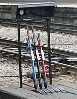
A set of points on the Strathspey Railway in Scotland. The facing bespeak lock in the middle will need to be withdrawn using the blueish lever (backside) on the left before the points themselves tin can exist moved using the black lever (front). In one case the points have been moved the lock volition be pushed in once more with the blue lever to lock the points in position.
A facing point lock (FPL), or point lock, is a device which, as the name implies, locks a prepare of points in position, as well every bit mechanically proving that they are in the right position. The facing point function of the name refers to the fact that they prevent movement of the points during facing moves, where a train could potentially separate the points (end upwardly going down both tracks) if the points were to move underneath the train. During abaft moves, the wheels of a railroad train will force the points into the correct position if they effort to move, although this may cause considerable damage. This act is known equally a "run through".
In the United kingdom of great britain and northern ireland, FPLs were common from an early engagement, due to laws beingness passed which forced the provision of FPLs for any routes traveled by passenger trains – information technology was, and all the same is, illegal for a passenger train to make a facing move over points without them beingness locked, either by a signal lock, or temporarily clamped in one position or some other.[11]
Joints [edit]
Joints are used where the moving points meet the stock-still rails of the switch. They permit the points to hinge easily between their positions. Originally the movable switch blades were connected to the stock-still closure rails with loose joints, but since steel is somewhat flexible it is possible to obviate this looseness by thinning a short section of the rail'south bottom itself. This can exist called a heelless switch.
Straight and curved switches [edit]
Turnouts were originally built with direct switch blades, which ended at the pointed end with a abrupt angle. These switches cause a crash-land when the train traverses in the turnout direction. The switch blades could be made with a curved point which meets the stockrail at a tangent, causing less of a bump, only the disadvantage is that the metallic at the point is sparse and necessarily weak. A solution to these conflicting requirements was found in the 1920s on the German Reichsbahn. The starting time step was to have different track contour for the stock rails and switch runway, with the switch runway being near 25 mm (0.98 in) less high, and stockier in the centre.
Point indicators [edit]
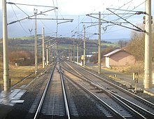
As it is difficult to see the lie of a switch from a distance, especially at night, European railways and their subsidiaries provide point indicators which are often illuminated.
Components gallery [edit]
-

A swingnose crossing: The point of the Five-shaped rail is moved to align the rail in the appropriate direction where the ii rails cross.
-
A basis frame contains a few levers for manually operating nearby points:
Blue lever: Release
Blackness lever: Points
Red lever: Signal -
A light industrial or k rails switch joint, where the points are joined to the closure rails past bolts through a "joint bar" or "fish plates"
-
-

Switches on rubber-tyred metros use conventional points on the standard gauge runway to guide trains. Rubber tires, rolling on concrete rollways, keep supporting the full weight of the trains as they become through switches. Guideways are provided in gild to ensure there are no gaps in the electrical power supply.
Types [edit]
Apart from the standard right-hand and left-manus switches, switches usually come in diverse combinations of configurations.
Slip switches [edit]
Double sideslip [edit]

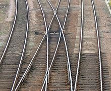
A double switch, or double slip. The points are set to connect the upper left and lower right tracks.
A double slip switch (double slip) is a narrow-angled diagonal flat crossing of 2 lines combined with 4 pairs of points in such a way as to permit vehicles to alter from one straight track to the other, alternatively to going straight beyond. A railroad train approaching the arrangement may leave past either of the two tracks on the opposite side of the crossing. To reach the third possible exit, the train must alter tracks on the slip and then reverse.
The arrangement gives the possibility of setting four routes, simply because only one road tin be traversed at a time, the four blades at each end of the crossing are often connected to movement in unison, and so the crossing can be worked past just ii levers or point motors. This gives the same functionality of two points placed end to end. These compact (albeit complex) switches usually are found only in locations where infinite is express, such equally station throats (i.due east. approaches) where a few principal lines spread out to reach any of numerous platform tracks.
In North American English, the arrangement may too exist called a double switch, or more colloquially, a puzzle switch. The Great Western Railway in the United kingdom used the term double compound points, and the switch is too known as a double compound in Victoria (Australia). In Italian, the term for a double switch is deviatoio inglese , which means English switch. Likewise, it is called Engels(e) Wissel in Dutch, and was chosen Engländer in German in former times.
Single slip [edit]
A single slip switch works on the same principle as a double sideslip, but provides for only one switching possibility. Trains approaching on one of the two crossing tracks can either continue over the crossing, or switch tracks to the other line. However, trains from the other rails can only continue over the crossing, and cannot switch tracks. This is normally used to permit access to sidings and improve safety by avoiding having switch blades facing the usual direction of traffic. To accomplish the sidings from what would be a facing direction, trains must continue over the crossing, and then reverse along the curved road (usually onto the other line of a double runway) and can and so move forrad over the crossing into the siding.
Outside slip [edit]

A double, outside skid in Heidelberg main station
An exterior slip switch is similar to the double or single skid switches described in a higher place, except that the switch blades are outside of the diamond instead of inside. An advantage over an inside slip switch is that trains can pass the slips with college speeds. A disadvantage over an within sideslip switch is that they are longer and need more space.
An exterior slip switch tin can exist then long that its slips do not overlap at all, as in the instance pictured. In such a case a single, exterior slip switch is the same as two regular switches and a regular crossing. An outside, double slip switch is almost the same equally a scissors crossover (see below), merely with the disadvantages:
- The two parallel tracks cannot exist used at the same time.
- The slips are not straight and thus have a limited speed.
Advantage:
- The crossing can be passed at full speed.
Due to the disadvantages over both the double within slip switch and the pair of scissors crossover, double outside slip switches are simply used in rare, specific cases.
Crossover [edit]

A scissors crossover: ii pairs of switches linking 2 tracks to each other in both directions
A crossover is a pair of switches that connects ii parallel rails tracks, allowing a train on 1 track to cross over to the other. Like the switches themselves, crossovers tin can exist described equally either facing or trailing.
When 2 crossovers are present in contrary directions, one afterwards the other, the four-switch configuration is called a double crossover. If the crossovers in unlike directions overlap to course an ×, it is dubbed a scissors crossover, pair of scissors crossing, or just scissors; or, due to the diamond in the center, a diamond crossover. This makes for a very meaty runway layout at the expense of using a level junction.
In a setup where each of the two tracks usually carries trains of only ane management, a crossover can exist used either to detour "wrong-track" around an obstruction or to reverse direction. A crossover tin can also join ii tracks of the aforementioned direction, mayhap a pair of local and limited tracks, and allow trains to switch from one to the other.
On a crowded system, routine employ of crossovers (or switches in general) will reduce throughput, as employ of the switch blocks multiple tracks. For this reason, on some loftier-capacity rapid transit systems, crossovers between local and express tracks are not used during normal rush hour service, and service patterns are planned around utilize of the unremarkably flying junctions at each end of the local-express line.
In Frg an functioning signal only consisting of a crossover is known as an Überleitstelle (abbreviated to Üst ).[12] At an Überleitstelle trains can transfer from i runway of a single or double track section of route to another track on a double track department on the same railway line. Depending on the prophylactic equipment provided, trains may run this other runway either past exception or routinely against the normal direction of traffic.
An Überleitstelle must have at least one turnout. On double tracked routes, single and double crossovers are mutual, each one consisting of two turnouts and an intermediate section. Very often – but non mandatory – the turnouts and block signals at an Überleitstelle are remotely controlled or gear up from a fundamental indicate box.
The official categorisation of an Überleitstelle every bit a blazon of junction get-go arose in Germany with the construction of high-speed railways. Previous to that at that place were already operating command points at which trains could only transfer from 1 track to another on the same road, but they were considered as junctions ( Abzweigstelle ). The latter are all the same used to refer to those places in stations which enable trains to cross from one route to some other.
Stub switch [edit]

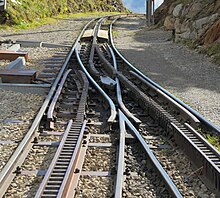
Closeup of a stub switch in Pennsylvania

A narrow gauge stub switch. (A further case of a stub switch is shown at "Iii fashion switch" below.) Note that this switch has an additional piece of movable rail instead of a frog.
A stub switch lacks the tapered points (point blades) of a typical switch. Instead, both the movable rails and the ends of the track of the diverging routes accept their ends cut off square. The switch mechanism aligns the movable rails with the rail of one of the diverging routes. In 19th century US railroad apply, the stub switch was typically used in conjunction with a harp switch stand.
The rails leading up to a stub switch are not secured to the sleepers for several anxiety, and rail alignment across the gap is not positively enforced. Stub switches as well crave some flexibility in the rails (meaning lighter rails), or an extra articulation at which they hinge. Therefore, these switches cannot exist traversed at loftier speed or past heavy traffic and and then are not suitable for main line use. A farther disadvantage is that a stub switch being approached from the diverging route that is not connected by the points would issue in a derailment. Even so another disadvantage is that in very hot weather, expansion of the steel in the track can cause the movable rails to stick to the stock rails, making switching impossible until the rails have cooled and contracted.
1 advantage to stub switches is that they work better in the snowfall. The sideways action of the point rails pushes snow to the side, instead of packing the snow between the points and the track in a more modernistic design.
Stub switches were more mutual in the very early days of railways and their tramway predecessors. Now, because of their disadvantages, stub switches are used primarily on narrow guess lines and branch lines. Some modern monorail switches use the same principle.
Three-way switch [edit]

A iii-fashion switch is used to split a railroad track into 3 divergent paths rather than the more usual 2. There are two types of three-way switches. In a symmetrical three-way switch, the left and right branches diverge at the same place. In an asymmetrical iii-way switch, the branches diverge in a staggered way. Both types of three-mode switches require three frogs.
The complexity of symmetrical switches usually results in speed restrictions, therefore three-way switches are most often used in stations or depots where space is restricted and low speeds are normal. Symmetrical switches were used quite ofttimes on Swiss narrow-approximate railways. Asymmetrical 3-way switches are more common, because they do not have speed restrictions compared to standard switches. Even so, because of their higher maintenance cost due to special parts as well as asymmetric wear, both types of iii-way switches are replaced with two standard switches wherever possible.
In areas with very depression speeds, like depots, and on railroads that had to be built very cheaply, similar logging railroads, 3-way switches were sometimes built as stub switches.
Plate switch [edit]

A narrow approximate plate switch
A plate switch incorporates the tapered points of a typical switch into a self-contained plate. Each point blade is moved separately by hand. Plate switches are but used for double-flanged wheels, with wheels running through the plates on their flanges, guided by the edges of the plate and the moveable blade.
Because plate switches tin can but exist used by double-flanged wheels and at extremely low speeds, they are typically simply found on mitt-worked narrow estimate lines.
Off-railer [edit]
The off-railer is a organisation of installing a turnout over and above some plain track, without having to cut or supervene upon that track. Information technology is useful for installing temporary branches on agricultural railways, and sidings for rails machines on mainline runway. Special ramps lift the wheels off the normal runway, and and then the off-railer curves abroad every bit required. Decauville has such a system.[thirteen] Information technology is a chip like a drawbridge crossing.
Interlaced turnout [edit]

An interlaced turnout is a different method of splitting a track into three divergent paths. It is an arrangement of two standard turnouts, i left- and 1 correct-handed, in an "interlaced" fashion. The points of the 2nd turnout are positioned betwixt the points and the frog of the commencement turnout. In common with other forms of 3 way turnouts an additional common-crossing is required. Due to the inherent complexity of the system, interlaced turnouts are usually simply used in locations where infinite is exceptionally tight, such equally station throats or industrial areas within large cities. Interlaced turnouts tin also exist found in some yards, where a series of switches branching off to the aforementioned side are placed then shut together that the points of one switch are placed before the frog of the preceding switch.[14]
Wye switch [edit]
A wye switch (Y points) has abaft ends which diverge symmetrically and in opposite directions. The name originates from the similarity of their shape to that of the letter Y. Wye switches are unremarkably used where infinite is at a premium. In Northward America this is also called an "equilateral switch" or "equilateral turnout". Common switches are more often associated with mainline speeds, whereas wye switches are generally depression-speed yard switches.
One advantage of wye switches is that they can have a coarser frog bending using the same radius of curvature than a common switch. This means that they requite ascent to a less astringent speed restriction than the diverging branch of a common switch, without having to resort to more expensive switches with a moving frog. For this reason they are sometimes used on a main line where it splits into two equally important branches or at the ends of a single track section in an otherwise double track line.
Run-off points [edit]

Trap points at the exit from a k
Run-off points are used to protect chief lines from stray or runaway cars, or from trains passing signals set at danger. In these cases, vehicles would otherwise roll onto and foul (obstruct) the primary line and cause a collision. Depending on the situation in which they are used, run-off points are referred to either as trap points or take hold of points. Derailers are another device used for the same purpose.
Catch points are installed on the running line itself, where the railway climbs at a steep gradient. They are used to forbid runaway vehicles colliding with another train farther down the slope. In some cases, catch points lead into a sand drag to safely stop the delinquent vehicle, which may be travelling at speed. Catch points are unremarkably held in the 'derail' position by a leap. They can exist prepare to let a train to pass safely in the downhill direction using a lever or other mechanism to override the spring for a brusk time.
Take hold of points originate from the days of the 'unfitted' appurtenances (freight) train. Every bit these trains tended to consist of either completely unbraked wagons (relying entirely on the locomotive's own brakes), or ones with unlinked, manually applied brakes (necessitating a stop at the top of steep downgrades for the guard to walk along the train and set the brakes on each wagon in turn), they as well lacked any mechanism to automatically restriction runaway cars. Catch points were therefore required to stop the rear portion of a poorly coupled railroad train that might break abroad whilst climbing a steep grade – although they would as well stop vehicles that ran abroad for any other reason. At present that trains are all 'fitted' (and broken couplings are far less common), catch points are mostly obsolete.
Similar to grab points, trap points are provided at the exit from a siding or where a goods line joins a line that may be used by passenger trains. Unless they have been specifically gear up to allow traffic to laissez passer onto the main line, the trap points will direct whatsoever approaching vehicle abroad from the master line. This may only result in the vehicle being batty, but in some cases a sand drag is used, specially where the vehicle is likely to be a delinquent travelling at speed due to a slope.
Derailers [edit]
A derailer works past derailing whatsoever vehicle passing over it. There are unlike types of derailers, only in some cases they consist of a single switch betoken installed in a rails. The indicate can be pulled into a position to derail whatsoever equipment that is non supposed to pass through.
Dual estimate switches [edit]

A dual gauge switch in Japan
Dual gauge switches are used in dual judge systems. There are various possible scenarios involving the routes that trains on each gauge may accept, including the two gauges separating or one gauge being able to choose betwixt diverging paths and the other not. Because of the extra runway involved, dual estimate switches have more points and frogs than their single gauge counterparts. This limits speeds fifty-fifty more than than usual.
A related formation is the 'classy' or rail substitution, where (usually) the common rail changes sides. These have no moving parts, the narrower estimate wheels being guided past guard rails as they transition from 1 track to another. The wider gauge only encounters continuous rail so is unaffected past the commutation. At dual gauge turntables, a similar arrangement is used to move the narrow gauge rails from one side to a primal position.
Rack railway switches [edit]
Rack railway switches are as varied equally rack railway technologies. Where utilize of the rack is optional, as on the Zentralbahn in Switzerland or the West Declension Wilderness Railway in Tasmania, it is common to place turnouts only in relatively flat areas where the rack is not needed. On systems where only the pinion is driven and the conventional rail wheels are idlers, such as the Dolderbahn in Zürich, Štrbské Pleso in Slovakia and the Schynige Platte rack railway, the rack must exist continuous through the switch. The Dolderbahn switch works by bending all iii runway, an operation that is performed every trip as the ii trains pass in the middle. The Štrbské Pleso and Schynige Platte Strub rack system instead relies on a complex fix of moving points which assemble the rack in the traversed direction and simultaneously articulate the crossed direction conventional rails. In some rack systems, such every bit the Morgan system, where locomotives always have multiple driving pinions, it is possible to simplify turnouts by interrupting the rack rail, so long as the interruption is shorter than the spacing between the drive pinions on the locomotives.[15]
Some systems use transfer tables instead to provide continuous rack. The Pilatus Railway has unusual switches that rotate on an centrality parallel to the track.
Switch diamond [edit]
A switch diamond at a junction in the United kingdom
Although not strictly speaking a turnout, a switch diamond is an agile trackwork associates used where the crossing angle between two tracks is likewise shallow for totally passive trackwork: the unguided sections of each rails would overlap. These vaguely resemble two standard points assembled very closely toe-to-toe. These would besides frequently use swingnose crossings at the outer ends to ensure complete bike support in the same way as provided on shallow bending turnouts. In Northward America these are known every bit Movable-Point Diamonds. In the Great britain, where the angle of deviation is shallower than 1 in 8 (center-line measure) a switched diamond will be found rather than a passive or fixed diamond.
Such switches are commonly implemented on the basis of increasing the safe crossing speed. Open blades impose a speed restriction, due to the potential of the crossing impact fracturing the rail as both wheels on each axle hit the crossing gaps well-nigh simultaneously. Switched blades, every bit shown in the photo, allow a much higher speed across the gap by providing an essentially continuous piece of rails across the gap on both sides.
The frog end of the switched crossing, despite nonetheless having a gap in 1 rail, is less problematic in this regard. The outer rail is however continuous, the fly runway (the part that turns out, after the frog gap) provides a gradual transition, and the check track avoids the possibility of points splitting. This can be seen in how, nether examination, the fly rails has a wider polished section, showing how the wheel load is transferred across the gap.
Single-bespeak switch [edit]

Single signal switches, known as Natural language and Obviously Mate switches, are sometimes used on freight railways in deadening speed performance in paved areas such equally in ports. In the United States, they are regulated by provision 213.135(i) of the Federal Railroad Administration Track Prophylactic Standards.
On streetcar (tram) systems using grooved rails, if the wheels on both sides of the car are connected by a rigid solid axle, merely one switchpoint is needed to steer it onto i or the other track. The switchpoint will be on inside track of the switch'southward curve route. When a streetcar enters the bend route of the switch, the bicycle on the within of the bend (the right side of the car on a right plough) is pulled into the turn, and through the axle, directs the wheel on the outside to too follow the bend.[16] The outside bike is supported for a short distance by its flange running in the groove.
Some low flooring streetcar designs utilise divide axles (a separate one-half-beam for the wheel on each side of the machine). Such streetcars are unsuitable for employ with single-point switches as there would be no machinery to transfer the force from the inner to outer wheels at switches.[16]
A single-point switch is cheaper to build, especially in street trackage, as there is no demand to link to a second switchpoint.[16]
Rotary switch [edit]

A downhill train awaits the inversion of a rotary switch to keep its journey on the Pilatus Railway.
Rotary switches, are sometimes used on cog railways to maintain alignment of the cog with ii unlike tracks. They are used on the Pilatus Cog Railway to allow upwardly-bound and down-jump trains pass each other on a grade while sharing the residue of the single rail.
A rotary switch rotates about its long axis to present a track connection to a chosen fix of tracks. Physically, information technology flips over (rotates almost its long axis 180 degrees) to connect to the called ready of tracks. One time the rotary switch is secured the train can proceed. Cog alignment is maintained in both positions.
Temporary points [edit]
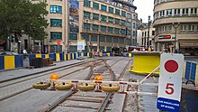
Temporary or 'Californian' points installed on tramline 81 at the junction of Avenue Louise and Rue Bailli (in French), a.k.a. Louisalaan and Baljuwstraat (in Dutch), Brussels
When a tram track is interrupted during repairs, a set of temporary points may exist placed on top of existing track to allow trams to cantankerous to the parallel track. These are known as Kletterweichen or Auflegeweichen in German, aiguillages californiens in French, and oplegwissels , klimwissels or Californische wissels in Dutch. They may be welded into place and allow trams to pass at walking pace.
Expansion joint [edit]
Expansion joints look similar a part of a railroad switch, only have a completely dissimilar purpose, namely to recoup for the shrinkage or expansion of the road bed - east.g. typically, a larger steel span - due to changes in temperature, to avoid dominicus kink.
Turnout speeds [edit]
Turnout speeds are governed by a number of factors.
As a general rule, the smaller the crossing angle of a turnout, the higher the turnout speed. In North America, turnouts are rated numerically, which represents the ratio of divergence per length every bit measured at the frog. A rule of thumb is that the rated speed of a switch (in miles per hour) is twice the numerical rating:
- No. fifteen: xxx mph (48 km/h)
- No. xx: 40 mph (64 km/h)
Higher speed turnouts have also been used in the United States:[4]
- No. 26.5: threescore mph (97 km/h)
- No. 32.seven: 80 mph (130 km/h)
In near other countries, switches are marked with tangent of crossing angle. For example, Russian federation and the balance of the Commonwealth of Independent States (CIS) apply the following designations:
- 1/half-dozen: sorting yards merely, whenever it is impossible to install a better switch
- one/9: 40 km/h (25 mph), the most common switch, installed by default
- one/11: 50 km/h (31 mph), used where passenger trains follow a diverging path. Swingnose crossing may be installed if required.
- 1/eighteen: 80 km/h (50 mph), used where either non-interruptible movement is required or the mainline diverges from the co-operative line
- ane/22: 120 km/h (75 mph), rarely used, high-speed lines just
In Germany, Austria, Switzerland, Czech Republic, Poland and other European countries, switches are described past the radius of the branching rails (in meters) and the tangent of the frog angle. The crossing may be direct, as in a crossover, or curved for other uses. The following designations are typical examples:
- 190-ane:9, the nearly common switch, for xl km/h on the branch rail
- 300-1:nine, preferred over 190-i:9 since the 1990s, for 50 km/h
- 500-1:12, for 60 km/h (signalled speed, capability: 65 km/h)
- 760-1:xiv, for 80 km/h
- 1200-1:eighteen.5, for 100 km/h
- 2500-1:26.5, for 130 km/h (in Czech Rep, signalled speed is 120 km/h) (swingnose but)
In New Southward Wales standard turnouts of tangential types include:
- i/7.5
- ane/viii.25
- see also NSW 1 in 8.25 crossing
- ane/10.5
- 1/12.0
- 1/xv
Uganda [edit]
![]() one in 16, for 100 km/h;[17]
one in 16, for 100 km/h;[17]
Full general [edit]
Other considerations include the type of turnout (e.g. normal nose, swing olfactory organ, slips), wear and tear issues, and the weight and type of the vehicle passing over. Speeds for a trailing movement may be higher than for a facing move. In many systems, speed limits vary depending on the type of train; for example, a turnout tin have a "normal" speed limit for locomotive hauled trains, and a higher speed for multiple unit or high speed trains.
Turnouts with curved or tangential switch blades accept higher speed than quondam mode turnouts with straight switch blades.
Older turnouts use the same rail department, shaved downward, for both stock rail and switch blade. Newer tangential turnouts use a stubbier rail department for the switch blade.
Assembly and transport [edit]
![]()
Transport of switches by track creates bug as they are so long and broad.
Turnouts are big pieces of track infrastructure which may be also big, wide, or heavy to transport in one piece. Special wagons can carry the pieces at approximately 45° from vertical, and then that they fit within the structure gauge. One time all the pieces take arrived, the turnout is assembled sleeper by sleeper on site. A set of turnouts may be trial assembled beforehand off site, to check that everything fits.
See likewise [edit]
- Abt automated turnout
- Centralized traffic command
- Double junction
- Gauntlet track
- Junction (rail)
- Level junction
- Minimum railway curve radius
- Monorail § Switching
- Rack railway switches
- Rail terminology (US/Great britain differences highlighted)
- Railway indicate
- Railway signalling
- Railway turntable
- Transfer table
References [edit]
- ^ Physicist Richard Feynman explains how a train stays on the tracks. BBC Tv set 'Fun to Imagine' (1983)
- ^ Rules 8.9, 8.15, and 8.eighteen, General Lawmaking of Operating Rules, Fifth Edition. (c) 2005 Full general Code of Operating Rules Committee.
- ^ Points and Crossings from Vossloh Cogifer
- ^ a b "63 FR 39343 – Automatic Railroad train Control and Advanced Ceremonious Speed Enforcement System; Northeast Corridor Railroads". Federal Railroad Administration. Retrieved 21 Oct 2012.
- ^ "Information on Wintertime Operation by Dutch Infrastructure Managing director Prorail". Prorail.nl (in Dutch).
- ^ "Drawings of Standard Railway Equipment Permanent Mode" (PDF). The LMS Society. London Midland & Scottish Railway. 1928. p. viii–17, 55–64. Retrieved 2022-03-06 .
- ^ Clark, Chuck; Davidson, Tom (Baronial two, 1991). "Boca Man among vii Killed in Amtrak Wreck". Ft Lauderdale Sun-Sentinel . Retrieved 2019-02-13 .
- ^ Edmonson, R.One thousand.; Sweeney, Steve (February iv, 2018). "NTSB: Misaligned Switch Directed 'Silver Star' into Parked CSX Autorack Train". Trains magazine . Retrieved 2019-02-13 .
- ^ Meyers, Marc A. (1994). Dynamic behavior of materials. New York: John Wiley. pp. v, 570. ISBN978-0-471-58262-five.
- ^ "Scene of the Accident". The Argus. Melbourne: National Library of Australia. 29 January 1906. p. vii. Retrieved 20 July 2011.
- ^ Requirements in regard to the Opening of Railways (1892), from the British Board of Trade
- ^ § 4, paragraph vi of the Eisenbahn- Bau- und Betriebsordnung or EBO (German language Railway Regulations).
- ^ Light Railway, LRRSA, April 2013, page 12.
- ^ Example
- ^ John H. Morgan, "Switching or Crossover Device for Traction Rack Rails Systems", U.South. Patent 772,736, Oct. 18, 1904.
- ^ a b c Steve Munro (10 Nov 2011). "TTC Unveils New Streetcar Pattern and Mockup". Retrieved 2016-10-02 .
- ^ Specifications Chinese Class 1; 50 kg/m rails
Further reading [edit]
- Winchester, Clarence, ed. (1936), "Switches and crossings", Railway Wonders of the World, pp. 1316–1322
- Cooper, Basil (February 1984). "Points, locks & bolts". Rail Enthusiast. EMAP National Publications. pp. sixty–61. ISSN 0262-561X. OCLC 49957965.
External links [edit]
- How a Railway Frog Point Works on YouTube
0 Response to "Two in One Drawlings Old Fashioned Train With a Big Light in the Front"
Post a Comment